Alexander A.Shpilman ( sah@nursat.kz )
The High-Voltage Generator of DS-state Elements
It was already
spoken about high-voltage generators of DS-state elements (see "Time
- Overtime")
in N2/01 Here we shall continue this theme.
|
|
|
|
|
|
The design of the generator of DS-state elements
(DSS elements) which is made as a capacitor with using of composit dielectric
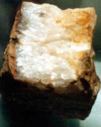
(see Fig.1) and a pulsing voltage on electrodes (see Fig.2) is discribed in N2/01. Our experiments have shown, that
is possible to use plates made of drusen crystal quartz (see Fig.3) as
anisotropic dielectric it with an angle of a cut is 45О in such a design. There are frequently cracks
between crystals of quartz through which an electric breakdown between
electrodes 2 and 3 occurs (see Fig.1) in such a plate. Therefore it is
necessary to cover such plate (to impregnate) with colophony (rosin) dissolved
in spirit or it is better to impregnate a mix of colophony with a stearin.
Preliminary, colophony and stearin should be melt in together. Then a little
alcohol is added to the mixture. The mixture should be carefully mixed up and
our plate of a cut of drusen crystal quartz should be covered by it.
The powder of carborundum (SiC) impregnated by
colophony works rather effectively in "a capacitor" variant of the
DSS generator. Such dielectric has rather big electric conductivity, therefore
it is recommended to use, for example, a long cylinder of such dielectric like
with electrodes at the butt-ends (see Fig.4).
|
|
It is not clear yet how DSS elements generated
by the carborundum influence on a man, therefore it is not recommended to experiment
the given design in the apartment. And also it is not recommended to switch it
on for the time more than it is necessary for the experiment. It is better to
carry out researches in the protective box from an electret film (see Shielding
packing ).
Reasoning
from the already known information an attempt to improve "Chizhevsky's
luster" is also interested to us.
|
|
||
|
|
|
|

For example, electrodes 1-5 are
placed between dielectric plates 6 (see Fig.5). The electrode 1 is made from aluminium,
2 is a thin tungstic wire, 3,4,5 are made from silver (or copper covered by
silver).
The pulsing voltage 15 kV + 130V is
fed on the electrode 1.
The pulsing voltage 15 kV is fed on
the electrode 2.
The pulsing voltage -15 kV is fed on
the electrode 3.
Electrodes 4 and 5 have
zero potential.
The corona discharge on a thin tungstic electrode 2 ionizes air, this induces ions with a positive charge. A difference of a voltage in 130V between electrodes 1 and 2 is strengthened by splitting between components of the "axion fields" with the negative and positive electric pseudo-charge (see Fig. 6) of these ions (the first act of DSS elements’ generation). The ions with a positive charge drift to the electrode 3 where their recharge occurs (change of a sign on a charge on the opposite one). Then the ions with the negative charge in the drift pass the electrodes 4, 5 and leave our design. The electrodes 4, 5 make the stream of air between the dielectric plates 6 more stable (from the left to the right of figure 5). With a stable stream of ions is provided also.
|
|
|
|
|
|
Thus, the generation of DSS elements (nitrogen
and oxygen) is take place at a potential difference of a pulsing voltage in
30kV. The negative charge of generated DSS elements raises their stability.
(Pay attention, ions and DSS elements are not the same). Naturally, it is
necessary to expect that the given device will generate more negative ions than
DSS elements. Nevertheless this generated stream of DSS elements is quite
perceptible for a man.
It is tempting to divide
generated DSS elements in space according to their polarization and to simulate
by it "A Place of POWER". This function of a small “places force”
is carried out by the construction represented in Fig.7 (The Imitator of a
"Place Power " IPP-1). Where, the electrodes 1, 2, 3 settle down
between the dielectric disks 7 with apertures in cent. The electrode 1 is an
aluminium ring, 2 is a ring from a thin tungstic wire, 3 is "a float"
from silver.
The pulsing voltage 15 kV + 130V is
fed on the ring 1.
The pulsing voltage 15kV is fed on
the ring.
The pulsing voltage -15 kV is fed on
"a float" 3.
The pintle from silver passes on the
axis of "the float" to which "short moustaches" of several
wires from silver 5 are soldered. They are located inside of two toroidal
electric coils 11 with are reeled up on the iron cones 9 atop of the
cone-shaped electric coils 10. The cone-shaped electric coils 10 create
magnetic field H (see Fig.8), this field is parallel to the axis of the
device.
The toroidal coils 11
create (magnetic) vector potential A directed as it is shown in Fig.9.
Such combination of electric coils in the sum creates vector potential of
spiral structure with opposite polarization in the top and in the bottom cone.
The toroidal coils are
protected from high-voltage breakdown by the dielectric cones 8.
The grids 6 are located
above the pintle and "short moustaches" for stabilization of corona
discharge on the ends of the pintle and the "short moustaches".
|
|
As well as in the design in Fig.5, the corona
discharge on the thin tungstic electrode 2 ionizes air and induces the ions by
a positive charge. The difference of a voltage in 130V between electrodes 1 and
2 is strengthened by splitting between the components of the "axion
fields" with a negative and positive electric pseudo-charge of these ions
(the first act of the DSS elements’ generation). The ions with a positive
charge carrying away the air, drift to the electrode 3 where their recharge
occurs (change of a sign of the charge on the opposite one). Then the ions with
a negative charge together with the stream of air leave upwards and downwards
along the axis (along the pintle of "the float") of the device
through apertures in the center of the dielectric disks 7. The corona discharge
above the pintle and "short moustaches" 5 increases concentration of
negative ions in the air and amplify the stream of air from the cones.
Against usual ions, the negative DSS ions go up
or down of the design according to their polarization. And then leave the
design in the corresponding direction.
Probably, it is better to place the design it
is horizontal position far away from the walls and other dense, properly sized
objects for saturation of a room by DSS ions. It is desirable to orient the
design on the magnetic field of the Earth (the top cone of the design should be
directed on the South Pole of the Earth).
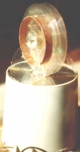
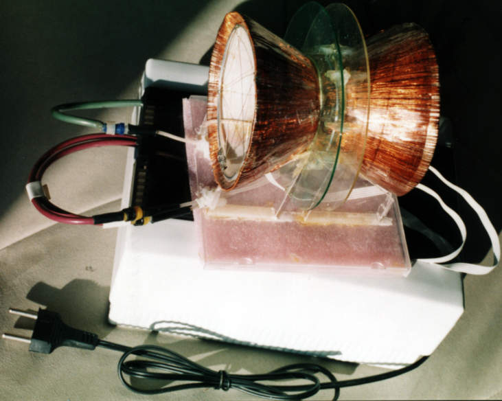
General view of a design can be seen in Fig.10.
|
|
You can buy the imitator of a "place power"
IPP-2 Information on E-mail: sah@nursat.kz |